Providing Buzzer & On/Off Relay Control Systems for over 20 years!
Product has a proven track record of running 24/7 in excess of 15 years
- Install & Setup Manual
- Full Software Installer
- Install & Setup Manual
- Technical Documents
Software Installation:
Please follow step two or you may get an error when running the software for the first time or will not be able to save your schedule.
Download The Current Install if you have no CD from the button above
- Downloaded the file to a directory
Install the software from the CD-Rom, or the download directory
- Run the “Setup_Buzzer_Controller_v2.0.exe” program
- If you are asked to reboot, follow the directions, then rerun the setup after the computer reboots
- If you wish to install the application on a network change the drive letter to the network drive letter
- Special Note: The software’s folder must be located off the root directory called “BUZZCTRL”
- For example “C:\BUZZCTRL”, “F:\BUZZCTRL”
- If the software has been installed to any drive other than “C:” you will have to edit the programs icon to reflect the proper drive letter.
- Click Start then Programs, then the Buzzer Controller Program Group
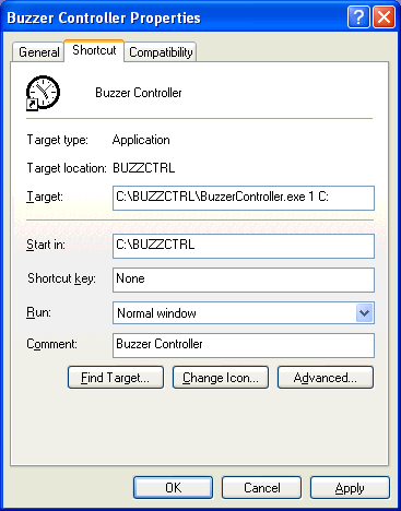
- Right click on the “Buzzer Controller” program icon then choose the properties item (see fig 1)
- Change the “C:” at the end of the “Target:” Line to the drive letter the “\BUZZCTRL” directory is on.
- Change the “1” to the number of the Serial Comm Port the hardware will be plugged into if needed.
The application can be installed on as many machines as you would like to be able to edit the alarm schedule on.
- Each machine should have access to the same “\BUZZCTRL” directory and have there program icon pointing to the correct drive
- If you modify the alarm schedule though you have to exit and reload the software on the computer with the buzzer controller hardware.

Figure 1
Edit Your Schedule:
- Load Buzzer Controller Application
- Note: During the install two sample .DAT files (ALARMAUX.DAT, and ALARM.DAT) will be installed. These are samples, you can delete them from the \BUZZCTRL directory when you want to add the schedule for your plant, or just modify them
- Enter the time in military time, the desired alarm pattern (A, B, or C), then check the days they will fire, finally you can enter a description of why this alarm fires.
- You can enter alarms out of sequence, when you click save it will resort them into chronological order.
When editing your schedule you can press- To Insert Lines (Ctrl + Insert) <- not really needed as the schedule will always re-sort when you exit the grid
- To Delete Lines (Ctrl + Delete)
- Remember to click “SAVE” when you are done editing your schedule
For The Machine That Is Running The Schedule:
- When the software is installed on the machine that will run the application, there is some command line options that can be used.
- Edit the programs icon to reflect the proper communications port, options, and drive letter.
Click Start then Programs, then the Buzzer Controller Program Group - Right click on the “Buzzer Controller” program icon then choose the properties item (see fig 1)
- Change the 1 to the proper communications port the interface cable is plugged into
- Change the “C:” to the drive letter the “\BUZZCTRL” directory is on.
- Add the command “PANEL” to run the schedule in panel mode where employees will not be able to modify the schedule
- For example “1 PANEL F:”
- When the software is running in PANEL mode, typing “6665” on the keyboard will restore it to it’s full size. If you mistype press “ESC” key then enter 6665 again. Entering “6565” will shutdown the Buzzer controller application.
- Add the command “HIDE” to run the schedule in Hidden/Stealth Mode
- For example “1 HIDE F:”
- You will need to CTRL+ALT+DEL and end the task to exit it.
Hardware Setup & Initial Power up:
- All wiring should be preformed by a certified electrician, and inspected.
- The Buzzer Controller should be mounted in a panel. or PVC box to keep it free from water or corrosive environments.
- The Aux Relay, if used should be mounted properly, and if it will power high volt/amp items for long periods it may need to be mounted on a heat sink.
- Damage resulting from improper hookup will not be covered by the product warranty
- Hardware vV1.5AC: (A/C Version)
- Attach Your AC Buzzers to The Relay’s LOAD 1 & 2 Terminals ONLY
- On the Tyco Electronics Relay this is terminals “1/L1″ and 2/T1”
- Attach Your AC Buzzers to The Relay’s LOAD 1 & 2 Terminals ONLY
- Plug The Included RCA Cable into the Side RCA Port marked “BUZ”
- The RCA Cable is pre-wired to the included A/C Relay. If it is not the Red Wire goes to Terminal “3/A1” and the back to Terminal “4/A2” of the included A/C Relay.
- Hardware v1.5DC: (D/C Version ~Phone Paging System)
- Plug The Included RCA Cable into the Side RCA Port marked “BUZ”
- Attach Your Contact Closure or your 0-60v, 3A D/C Current source to;
- The Terminals “1” and “2” of the included Crydom D60 Relay
The Leads on the RCA Plug Included (if it is the Pre-May 1st/2012 Included Relay: Coto Technologys 9001 Series Reed Relay Cable) - This could be the two screw terminals on your phone systems tone generator, or other device that uses a contact closure to trigger your paging sound or desired chime
- The Terminals “1” and “2” of the included Crydom D60 Relay
- Continuing the Setup (A/C or D/C)
- The RCA Jack marked “AUX” at the front of the unit is for the Optional AUX On/Off, or Alarm Zone 2 Relay Connector
- Never attach any current to RCA Connector, an Optional Cable & Relay is available, (or can be user created) for connection to a 5v Triggered Relay ONLY!
- This connector can be used to control A/C Currents both sold as a add on kit with the connecting RCA cable include
- A/C Currents using the same Tyco Electronics Relay
- D/C Currents using the Crydom D60 Relay
- Turn the controlling computer off
- Plug the interface cable into the controller hardware, and computer serial port.
- Attach 9v Power Adaptor, and plug it into the wall
- The Green LED Should Glow, and stay on. This Green “Ready” LED will only light if the internal CPU in the unit starts up and is ready to accept commands.
- Turn on the controlling computer
- Load Buzzer Controller Application and press “HW Status” button
- This should report the version number of the microcontroller in the interface box in place of the word “READY”
If the version of the chip does not come up the most common problem may be the serial cable is plugged into the wrong comm port #, or the software is told to use the wrong comm port. (Refer to Software Install Instructions) - Press “Test Alarm ‘A'” to test the Alarm (Your Buzzers should sound for about five seconds)
The Green LED will turn off when the Alarm Relay is Turned On, and will return to the Green READY Condition when the Alarm is finished.
- This should report the version number of the microcontroller in the interface box in place of the word “READY”
- The RCA Jack marked “AUX” at the front of the unit is for the Optional AUX On/Off, or Alarm Zone 2 Relay Connector
Older Hardware Versions;
- Hardware v1.1: The Longer Leads coming out of the Buzzer Controller are for the Optional AUX On/Off Relay.
- Never attach any current to ANY leads coming from the buzzer controller they are for Triggering a +5v Relay ONLY!
- For example the leads plugged into Terminals 3 & 4 using the default A/C Relay
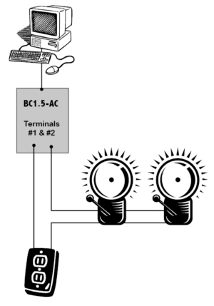
Simple Block Diagram:
- The Black / Hot wire is connected to the relay’s High Current terminals, the hookup is similar to wiring a light switch, where here the light switch is the Relay.

